Space Ranger uses automated image detection algorithms to determine the position of fiducial markers and to identify tissue boundaries. Through extensive testing on a diverse range of H&E images, tissues, and samples, 10x Genomics has verified the robustness of these detection algorithms. However, for fluorescence images, or in cases where the fiducial markers are obstructed or tissue boundaries are unclear, manual fiducial alignment, and tissue outlining are necessary.
To address this need, Loupe Browser provides the Visium Manual Alignment wizard. This wizard enables users to interactively align an image to the slide's fiducial marker locations, perform precise tissue selection using a suite of tools, and export the manual alignment for use in a Space Ranger run. Loupe Browser also includes an option to load an additional overexposed capture to facilitate fiducial selection for fluorescence images. This capture can be incorporated as an additional channel in the same image file or as a separate image file, depending on the imaging system's capabilities. However, it is important to note that this capture is excluded from downstream analysis in Space Ranger and Loupe Browser.
The following page illustrates the alignment process for a single-channel brightfield image and a multi-page fluorescence image, highlighting the steps that differ between the two.
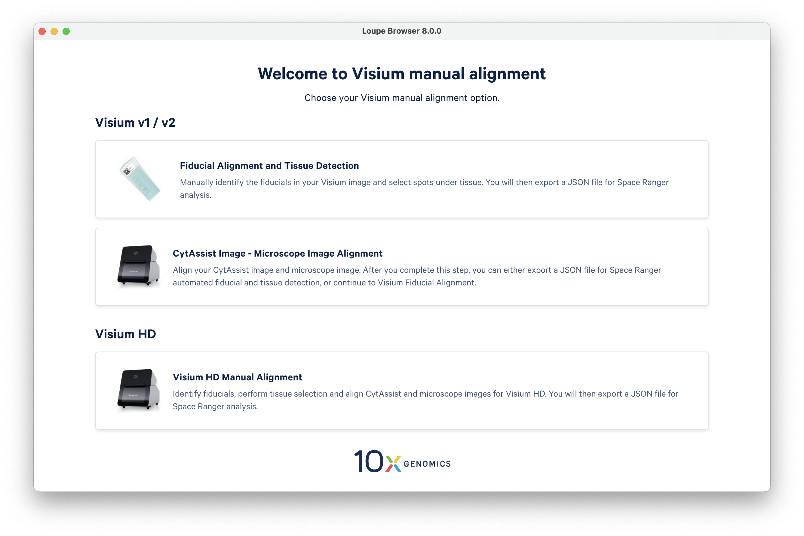
Loupe Browser's Visium Manual Alignment wizard can be accessed from the main panel on the start page. Simply scroll to the bottom of the panel and click on the link to launch the alignment wizard in a new window.
The landing page presents users with three options. Click on the first option, Fiducial Alignment and Tissue Detection.
A pop-up window will appear, listing the steps required for completing the alignment process.
The Visium Manual Alignment wizard accepts the same types of image files as Space Ranger, including .qptiff format.
For more information on recommended input image formats and other details, please refer to the input image recommendations page.
| Image Type | Image Format |
|---|---|
| Brightfield Image | 24-bit color TIFF/BigTIFF or a JPEG |
| 16-bit grayscale TIFF/BigTIFF or a JPEG | |
| Fluorescence Image | 8 or 16-bit grayscale single, multi-page TIFF/BigTIFF |
| 8 or 16-bit grayscale multiple single-page TIFF/BigTIFF or a JPEG | |
| 24-bit single colored image TIFF/BigTIFF or a JPEG | |
| CytAssist Image | 24-bit color TIFF |
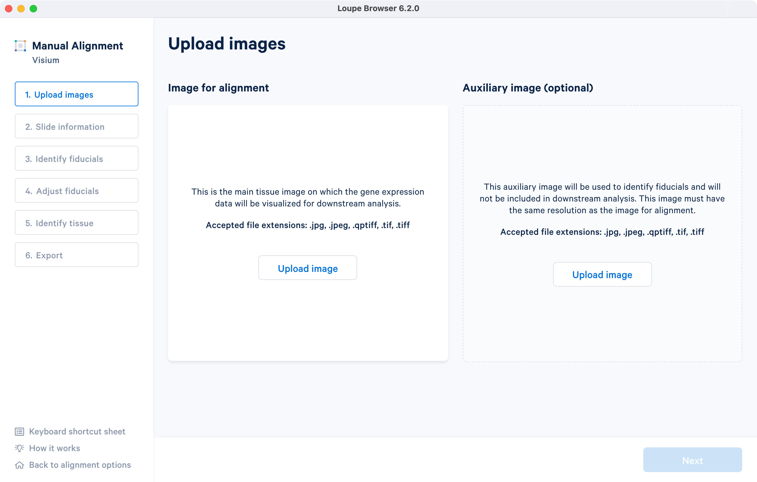
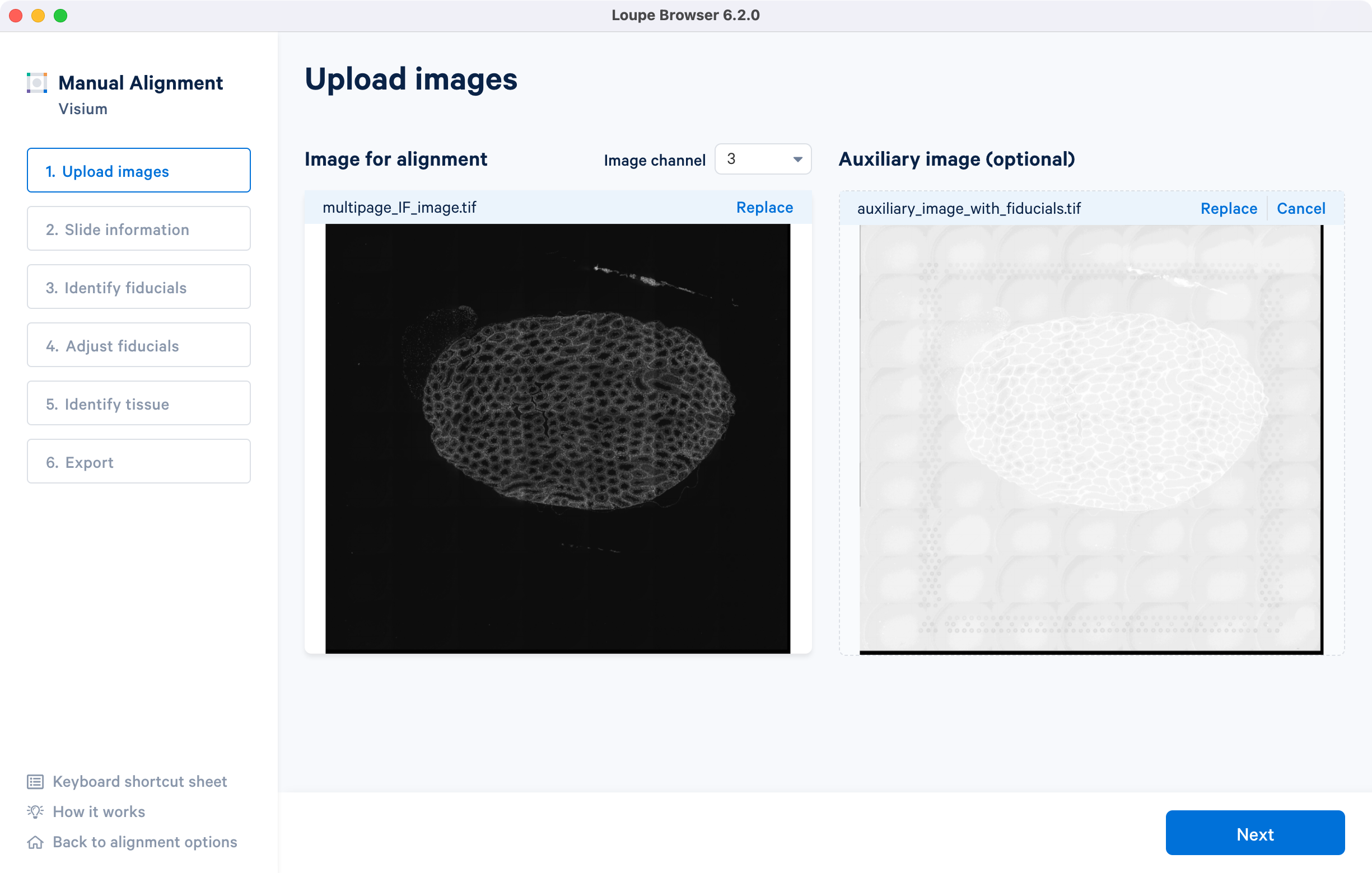
Click on Upload image under the Image for alignment panel to filter your filesystem for compatible image files. Selecting a file triggers a brief loading process. If the computer has insufficient RAM to efficiently load the image, the alignment wizard requires confirmation to continue. Note that clicking on the How it works on the lower left corner brings up the pop-up window.
Select the section corresponding to the different starting image types.
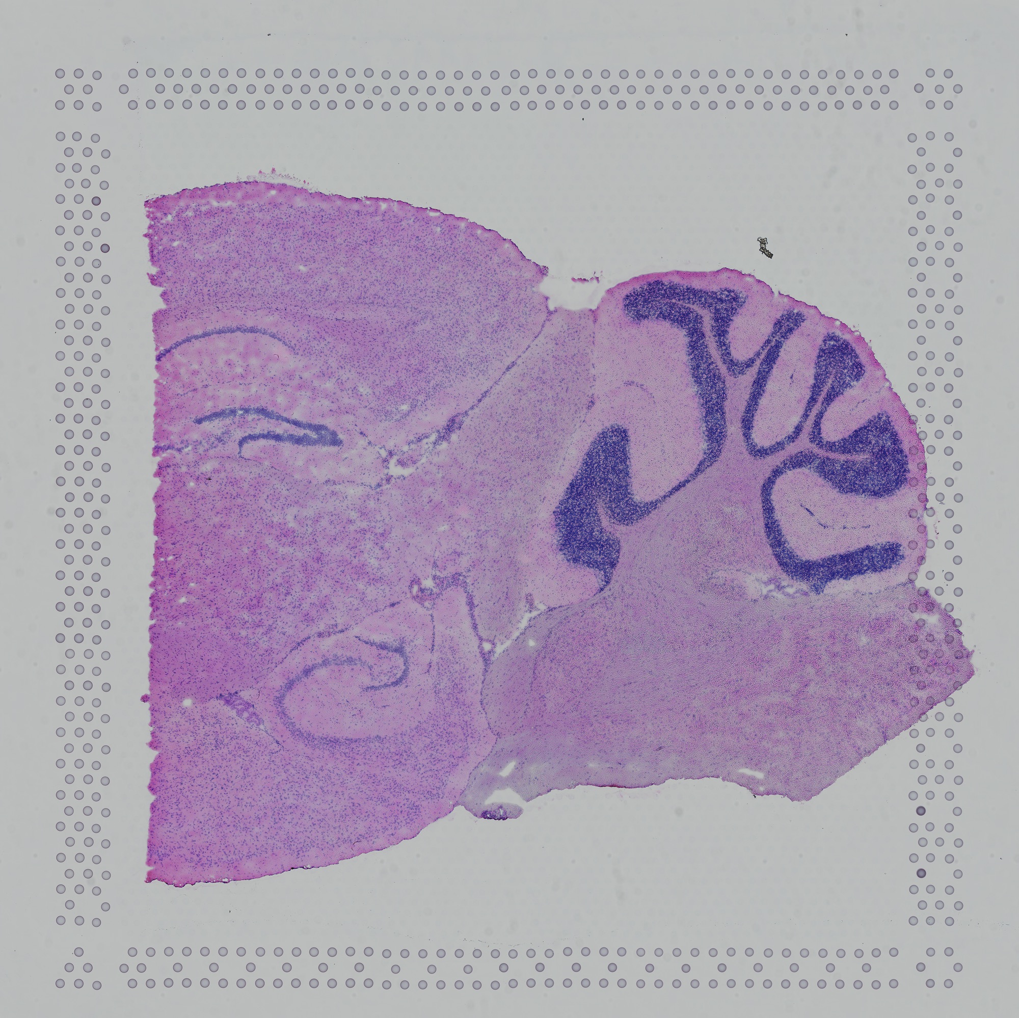
The tutorial will use the following resources for the H&E-stained brightfield image.
- Image: Download
- Slide serial: V19L29-035
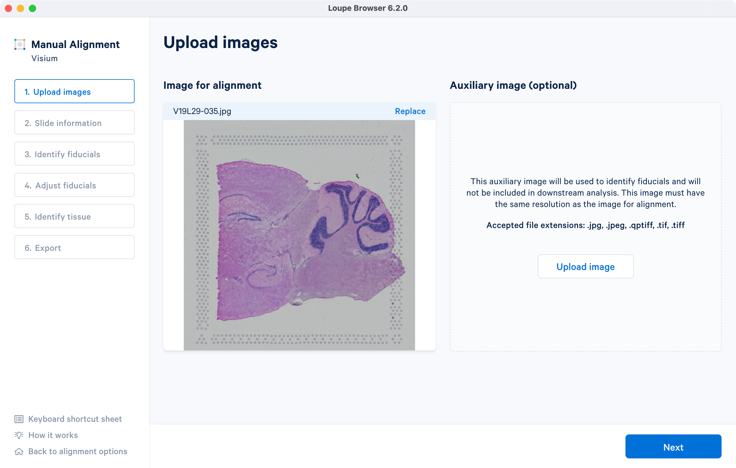
- Capture area: A1. Once the image is loaded, the preview image appear, as shown below. Successful upload of the image will make Next available to click. Use the Replace option located at the top right corner above the image preview to change the loaded image.
The tutorial will use multi-page fluorescence image included in human prostate FFPE public dataset.
- Image: Download
- Slide serial: V11J26-076
- Capture area: D1
After successfully uploading an image for alignment, a preview image will appear on the screen. The 'Next' button will become available for clicking, allowing you to proceed to the next step. If you need to change the loaded image at any time, use the 'Replace' option located at the top right corner above the image preview.
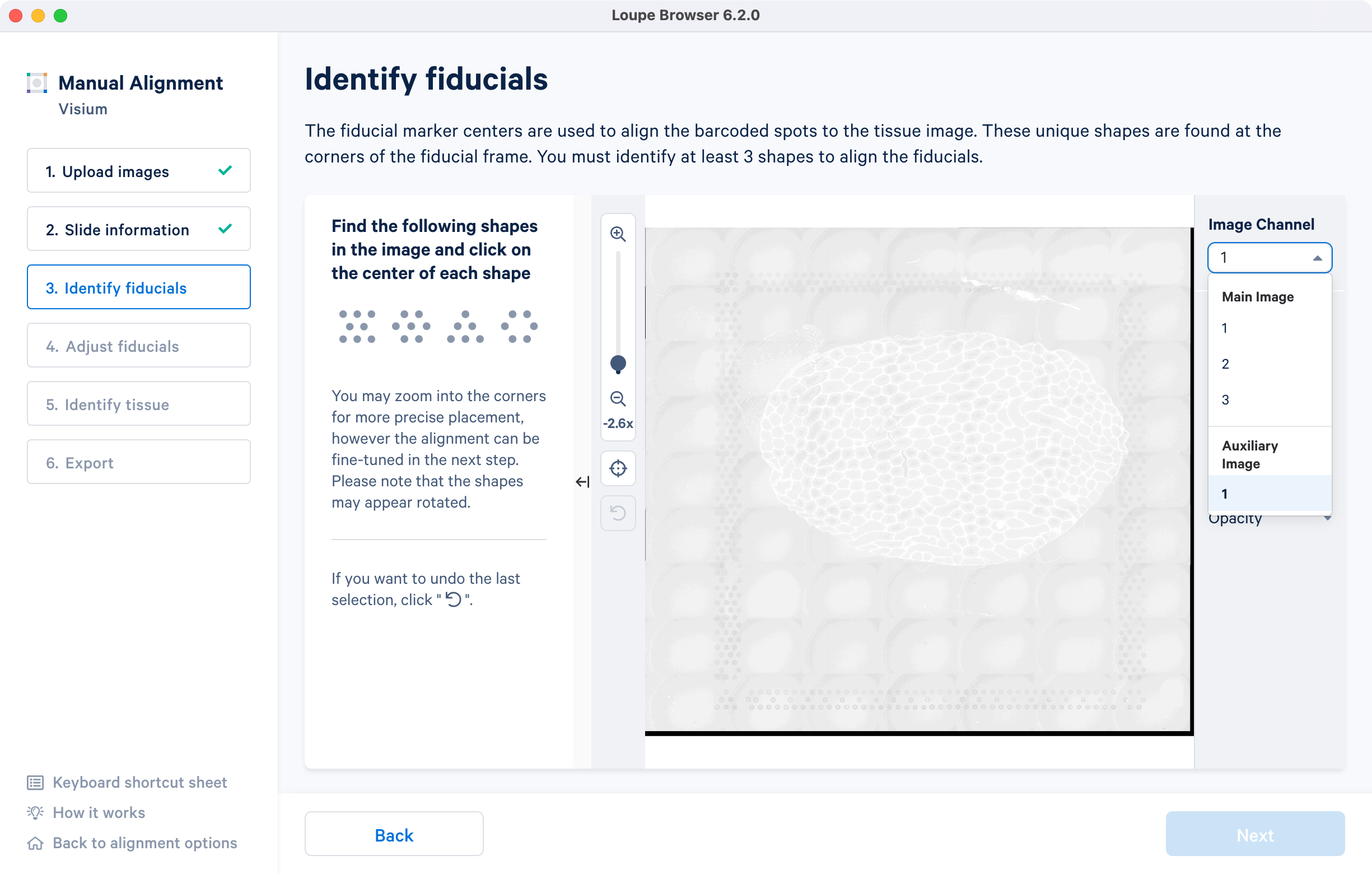
For multi-page fluorescence images, the fiducial markers and/or tissue may only be visible in a single page, as demonstrated in the tutorial dataset. To change the active page selection, use the 'Image channel' dropdown located throughout the alignment wizard. This will allow you to select the desired page for alignment.
If you have multiple single-page fluorescence images, there are three possible scenarios for aligning them:
-
You can supply the red channel image, which will have visible fiducial frames and visible tissue boundaries that can be used for image segmentation.
-
You can supply the red channel image or an overexposed image as an auxiliary for fiducial alignment, and use an image from a different channel for segmentation. The auxiliary image is excluded from analysis by default.
-
If the red channel includes a fluorescence signal of interest along with the fiducial frame, but does not have good tissue visibility, you can set the red channel as the auxiliary image for manual alignment and supply all channel images as input to
spaceranger count.
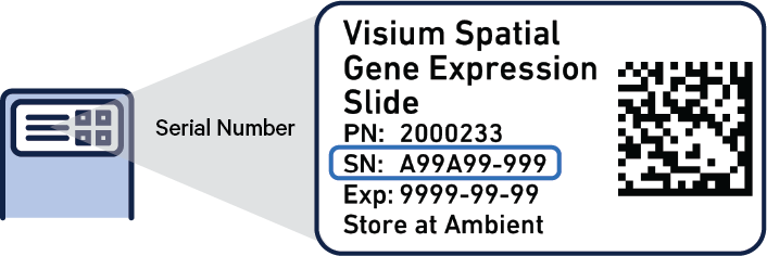
The Visium slide serial number and capture areas are important parameters that are specified in this step.
| Capture Areas | Slide Serial Number |
|---|---|
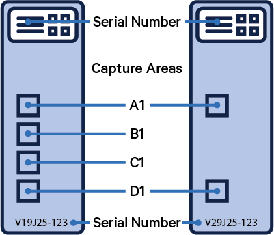 |  |
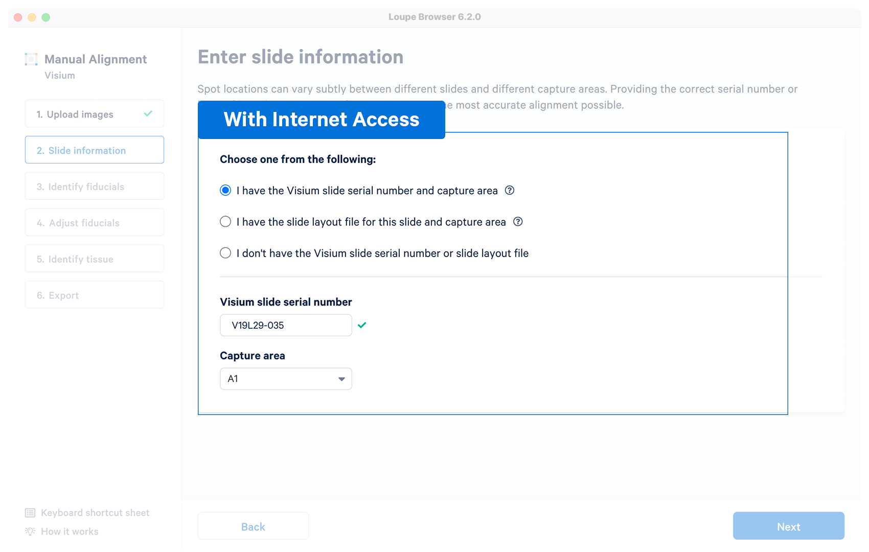
There are three options for entering slide information in the Visium Manual Alignment wizard.
| Loupe Option | Internet Access | Details |
|---|---|---|
 | Yes | The alignment wizard will download the layout file associated with the supplied serial number. The alignment wizard shows a prompt if the slide number is invalid, or the machine does not have an internet connection. Capture area selector is visible after a successful entry. |
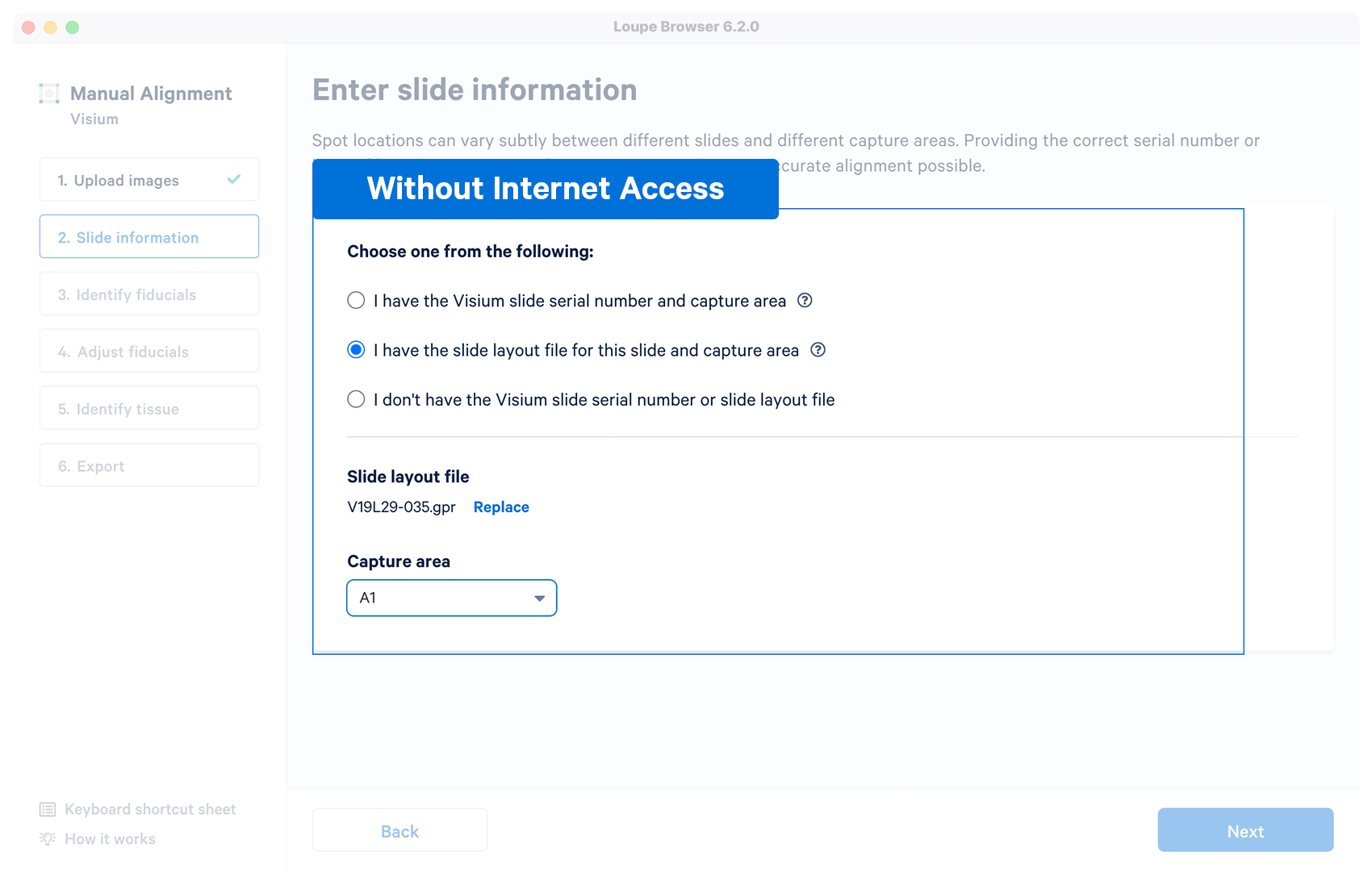 | No | User downloads a layout file in {"gpr"} format for a Visium slide before running the manual alignment. Once the file is loaded and validated, the capture area selector is visible. |
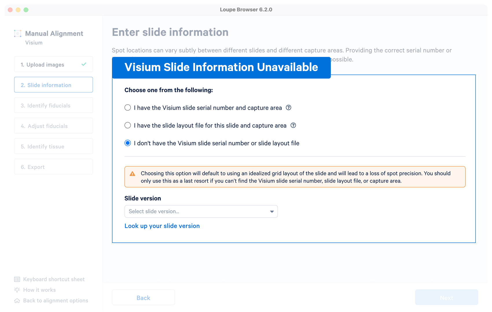 | Optional | The alignment wizard uses an idealized grid layout in the alignment step corresponding to the slide version which can be choosen from the drop down menu. If unsure, click on Look up your slide version which will open a pop-up window with the slide fiducial frames for reference. The typical per-spot difference between the default layout and a specific slide is within 5-15 microns, significantly smaller than the width of each spot. |
Select the section corresponding to the different starting image types.
If you have internet access, enter the following slide serial number and select the capture area from the dropdown menu. Appearance of a indicates successful retrieval. The slide number can be directly changed in the box.
- Slide serial: V19L29-035
- Capture area: A1
Alternatively, if internet access is not available, download the slide layout file in gpr format and upload it to the alignment wizard.
- Slide layout file: V19L29-035.gpr
- Capture area: A1
If you have internet access, enter the following slide serial number and select the capture area from the dropdown menu. Appearance of a indicates successful retrieval. The slide number can be directly changed in the box.
- Slide serial: V11J26-076
- Capture area: D1
To run the tutorial without internet access, you can [download slide layout file] in {"gpr"} format and upload it to the alignment wizard.
- Slide layout file: V11J26-076.gpr
- Capture area: D1
During this step, you will need to adjust the position of the image to match the spot locations on the slide layout file. The alignment is performed in two stages: coarse-grained alignment and fine-grained alignment. In the coarse-grained alignment, the centers of the fiducial markers are identified and used to align the image. In the fine-grained alignment, you will need to make small adjustments by dragging the image to match the spot locations more precisely.
To perform the coarse-grained alignment, select three or more fiducial markers in the image by clicking on their centers. The fiducial markers should be well separated from each other and located in different regions of the image. After selecting the fiducial markers, the alignment wizard will automatically calculate the transformation needed to align the image with the slide layout file. If the alignment is successful, you will see a green checkmark and you can proceed to the fine-grained alignment.
To perform the fine-grained alignment, you can use the cursor to drag the image and align it with the spots on the slide layout file. You can also zoom in and out of the image to make precise adjustments. Once you are satisfied with the alignment, click on the "Save alignment" button to save the alignment information.
Some additional features and functionality added to Loupe Browser v6.2 (and later) for manual alignment include:
- The ability to manually align using any three corner fiducial markers, which can also be chosen in any order.
- The ability to zoom into the image using the zoom sliders.
- The ability to use keyboard shortcuts for key actions.
- The Auto function that apply uniform brightness scaling across all pixels in the image.
- The ability to collapse the instruction panel to expand the image window.
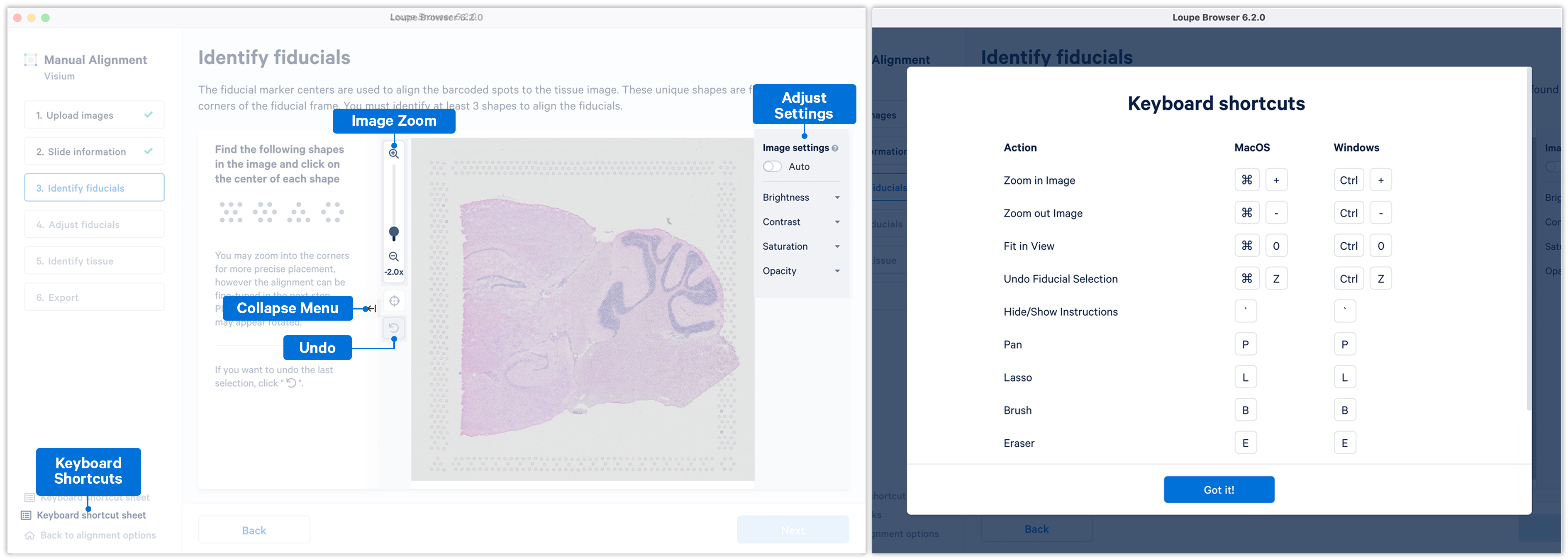
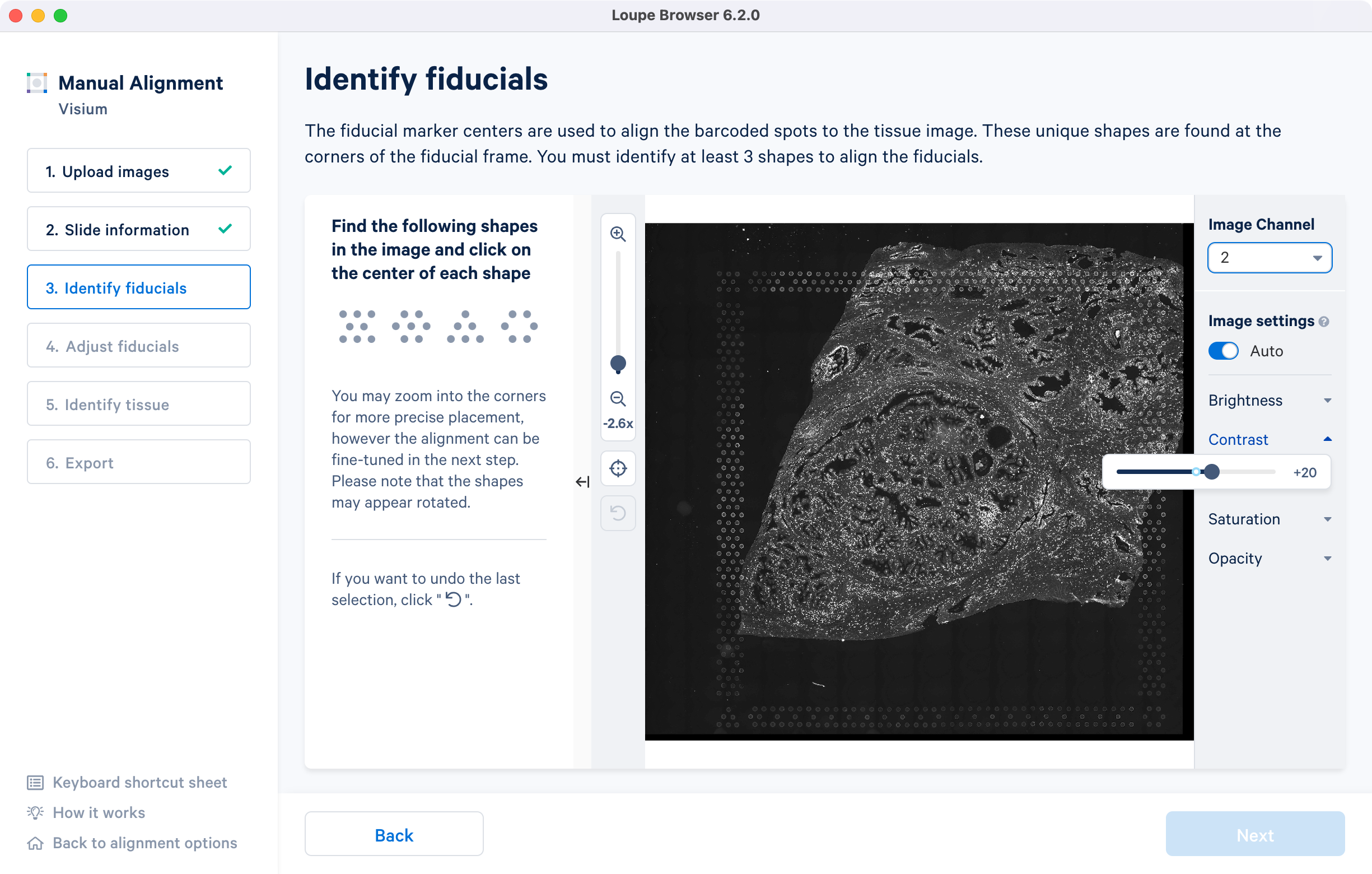
If the fiducial markers or tissue boundaries are dim, the brightness, contrast, saturation, and opacity of the image can be adjusted manually in the alignment wizard. When set to on, the Auto toggle adjusts the brightness of the image across all the pixels to enhance the dark and bright pixels by mapping the original image brightness values [min, max] to a new range and rescaling it back to the full brightness spectrum [0, 255]. Note that the Auto toggle is independent of the manual image settings and can be used in combination with one or more of the other image settings.
For multi-page fluorescence images, or when using an auxiliary image, it is important to begin by selecting a page where fiducials are most clearly visible. Use the Image Channel dropdown to select the correct page. This may be an overexposed page in the same file that you plan to discard downstream in your analysis.
If an auxiliary overexposed image was loaded in the previous step, it will be accessible as an additional option in the Image Channel dropdown at the Identify fiducials step for fiducial selection. This image must have the same resolution as the first image loaded for alignment.
Visium slides have four unique fiducial corner shapes.
| Fiducial Markers | Shape |
|---|---|
| Hourglass | |
| Filled Hexagon | |
| Open Hexagon | |
| Triangle |
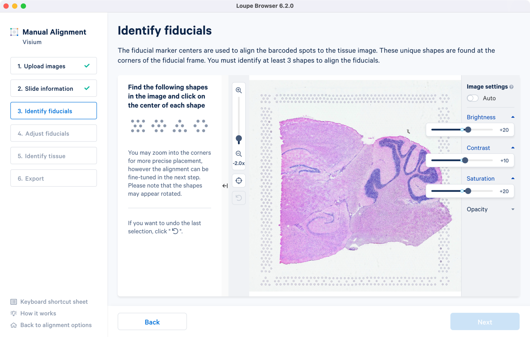
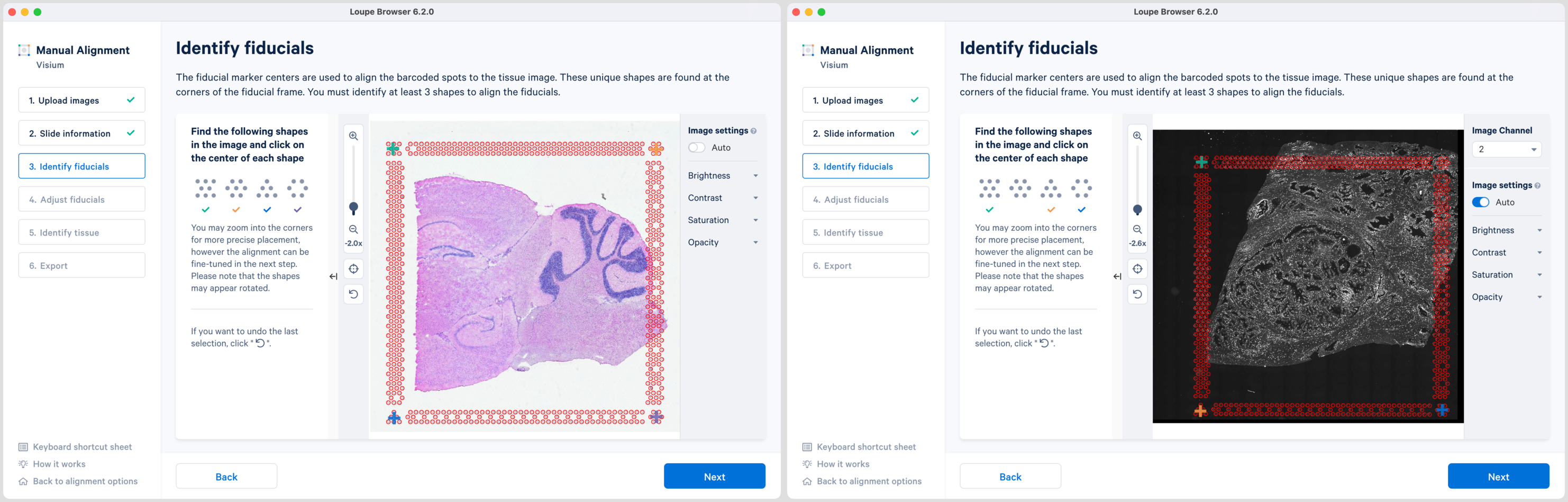
Alignment instructions are located on the left side of the page, and the alignment tool is on the right. It is important to follow the instructions carefully, as prompts change subtly at each step and it is critical to map each unique shape correctly.
Selection of each fiducial corner results in a colored + on the image and a matching ✓ on the instruction panel. Successful marking of at least three corners results in a red fiducial frame overlaid on top of the image. Click ![]() to revert selections at any time.
to revert selections at any time.
Appearance of the red fiducial unlocks the Next butoon to continue to step 4, Adjust fiducials.
While the placement of the red frame usually matches the fiducial frame on the image, in some instances fine-grained tuning may be required. In this step, you can achieve this by dragging the corner + shapes to adjust the alignment of the red spot outlines to the fiducial frame in the image. Zoom in over the frame to identify misalignments and correct them by clicking and dragging the +. There are three options to zoom into the image using either the mouse wheel, zoom slider, or keyboard shortcuts.
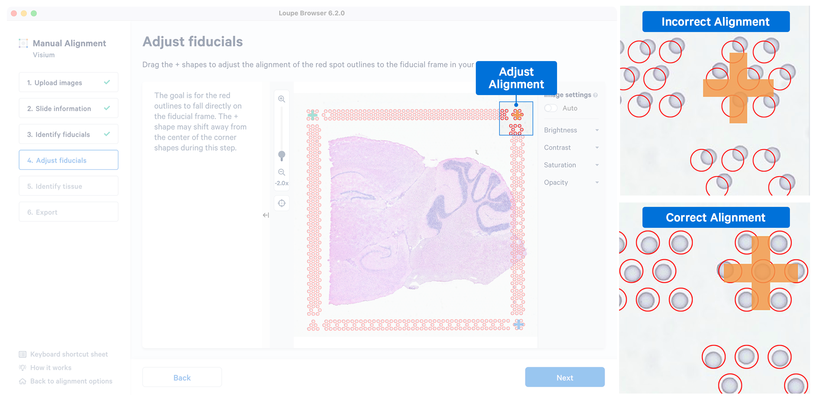
While fine-grained tuning is highly recommended to avoid any alignment errors, this step is optional and you can click Next to continue.
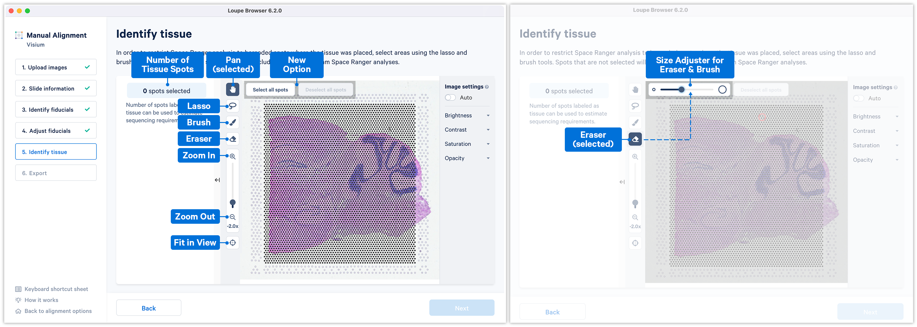
Accurate tissue boundary selection yields higher-quality data, lessens the likelihood of background-driven clusters, and provides accurate spot counts for fine-tuning sequencing parameters. When starting on the Identify Tissue page, the barcoded spots, with location inferred from the previous alignment step, are drawn on top of the image, as shown below. A toolbar to the left of the image provides a variety of options to perform both coarse-grained and fine-grained tissue selection.
For multi-page fluorescence images, the page that contains the clearest tissue boundaries may be different from the page that most clearly shows the fiducial markers. The active page can be changed by clicking on the Image Channel dropdown under the tissue alignment instructions. For the tutorial dataset set the page to 3 for this step.
Key details for when using the tools:
- Zoom can be independently applied in combination with any of the tools
- All the four main tools Pan
 , Lasso
  , Brush
  and Eraser
  can be operated only one at a time
 - Use the Fit in View
 anytime to restore the image to the default view.
There are two possible ways to select the tissue-associated spots which appear green upon selection:
-
Use of Select all spots and pruning using a combination of Lasso
and the Eraser tool. This is particularly useful when the tissue section occupies a large portion of the capture area.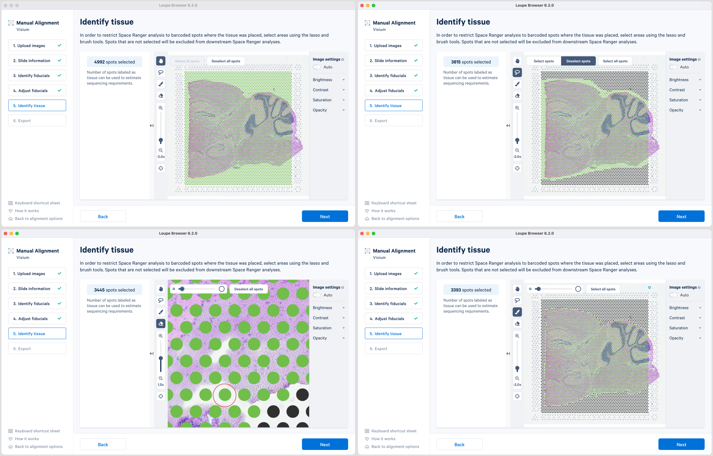
-
Use of a combination of Lasso
, Brush and Eraser tools to select the tissue regions. Lasso can be used to select large areas of tissue while precise selection can be achieved using the combination of Brush and Eraser, especially around the tissue boundaries.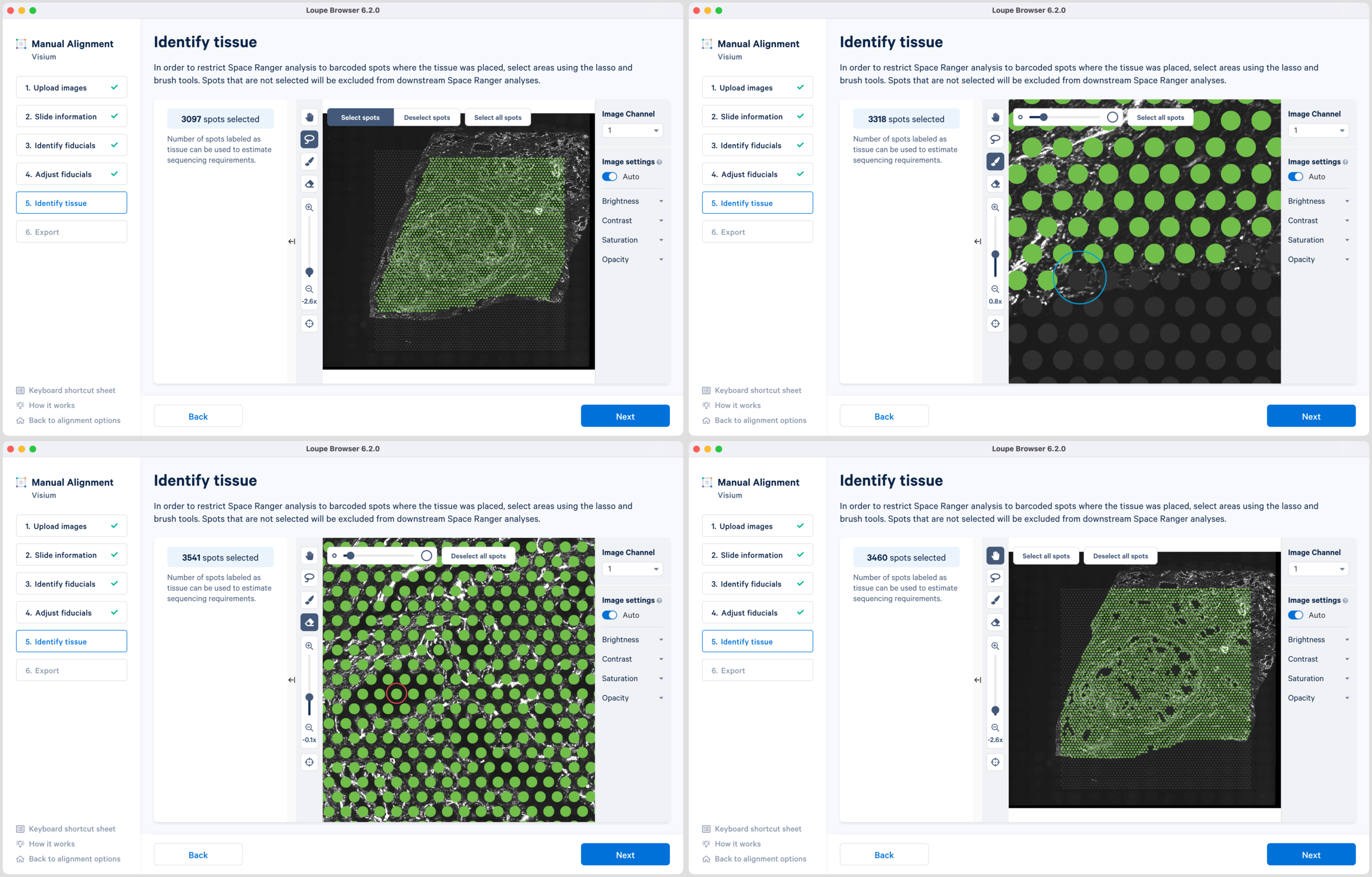
/>
Note that you can return to previous steps in the alignment wizard to fine-tune, make adjustments, restart alignment, restart tissue detection, or enter different data. If alignment is satisfactory, click Next to continue to the last step in the manual alignment workflow.
The final step shows the complete fiducial spot alignment and tissue selection. Click Export alignment JSON file to generate a JSON file.
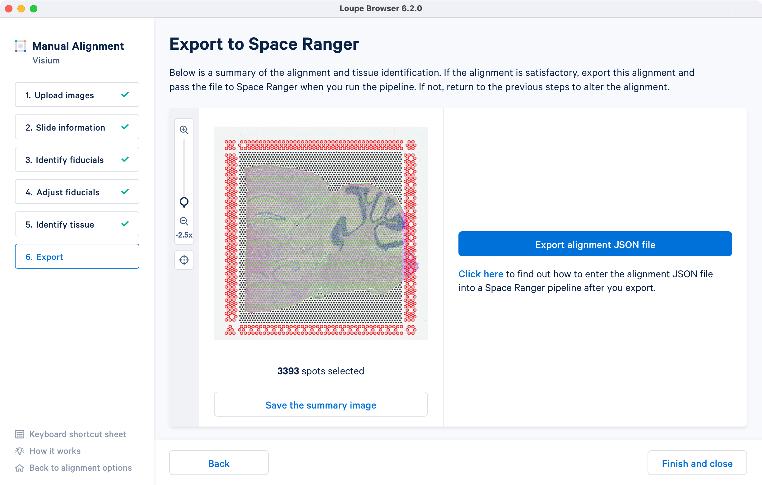
The image roughly mirrors the alignment preview shown in a Space Ranger web summary file. Use Save the summary image option for record-keeping purposes.
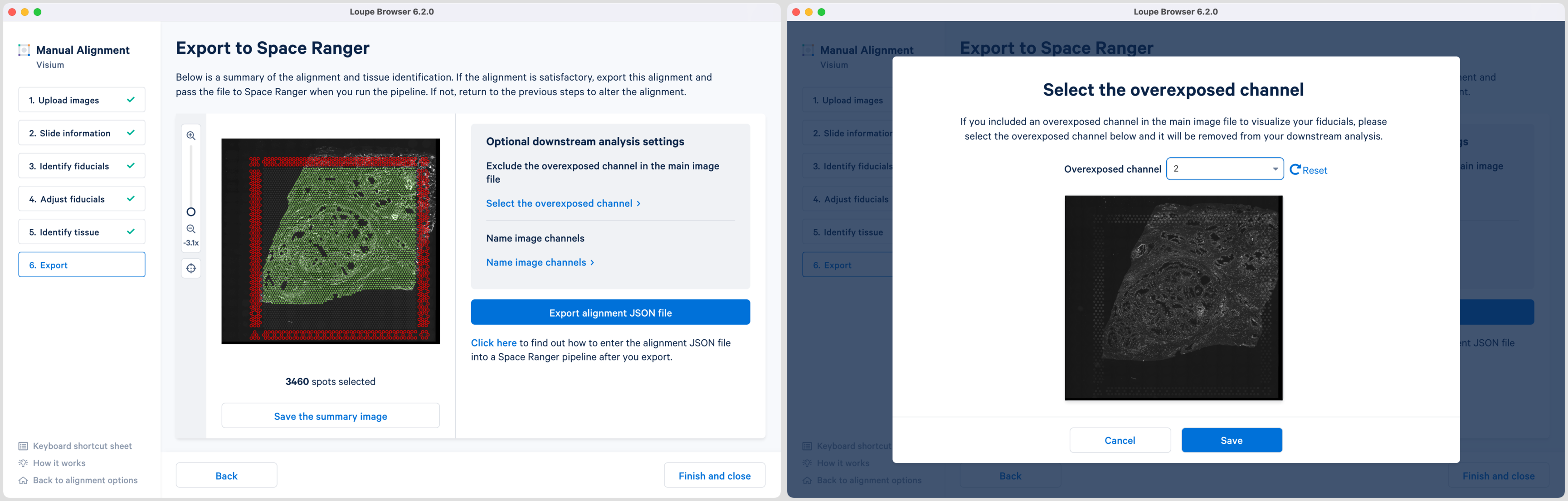
For multi-page fluorescence images where an overexposed capture was added as a page in the main image file, there is an option to exclude this page from downstream analysis. This is recommended to ensure that the tissue is clearly visible in the web summary and Loupe Browser analysis. Click Select the overexposed channel option, and in the pop-up window, select the page and click Save to exit. An auxiliary image will be excluded by default.
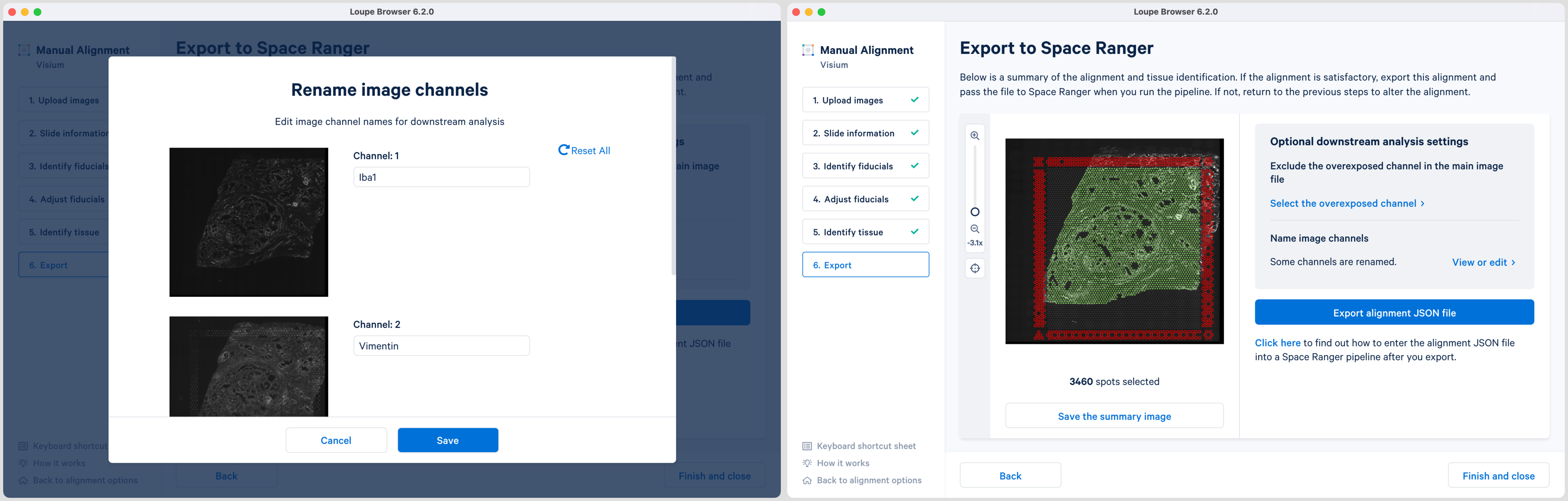
Loupe 6.2 also introduces the ability to name the fluorescence channels for multi-page TIFF images. The pop-up window is auto populated with the number of channels based on the input image. Click the Name image channels option and in the pop-up window, type the name in the box under each Channel number and click Save to exit. By default, the channels are named as channel n where n denotes an integer number starting at 1. It is possible to name only a subset of the channels and the remainder will follow the default channel name scheme. All channels, including the overexposed channel if applicable, are shown in this view.
The export page is now updated to indicate the named channels. Click View or edit to view the changes in the pop-up window. If channel names are provided in Loupe Browser, then Space Ranger will use these for column names in the barcode_fluorescence_intensity.csv file and in the cloupe.cloupe file.
The path to the generated JSON file is provided to spaceranger count pipeline through the {"--loupe-alignment"} argument. For workflows involving the CytAssist image, the Loupe alignment file can contain either both manual image registration and fiducial alignment information, or only the manual fiducial alignment information. It is important to make the alignment file available to both spaceranger count and the computing environment where the pipeline is run.